Characteristics
-
Field of use
-
Technical aspects
-
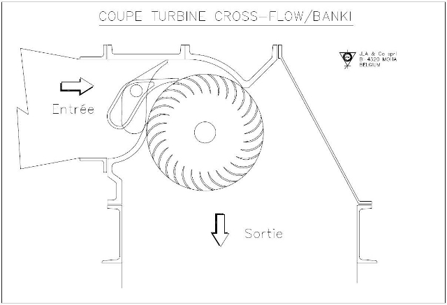
The cross-flow principle
Field of use
The graph below displays the JLAKit turbine’s field of use. It partially overlaps with that of the JLA29, produced by JLA Hydro SPRL since 1988.
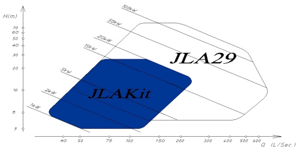
This turbine is suited to sites with a gradient of between 3 and 25 metres. The operable flow capacity for the machine is between 20 and 220 L/s. This covers many sites which can be operated with a limited level of civil engineering.
Technical aspects
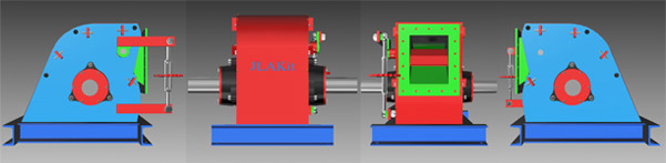
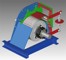
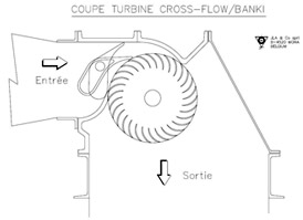
Identification: JLAKit cross-flow turbine, also known as “Banki”. It incorporates the JLA29 rotor (diameter: 292 mm), whose blades are specially profiled in order to optimise its yield.
Water inlet: horizontal.
Flow control: manual, “wing valve” type.
Inlet width: limited to a maximum of 300 mm, to be determined according to the flow and head site's characteristics.
Recommendations: in light of the design of the JLAKit, it is not intended to work in "succion", i.e. to harness the head of water situated between the axis of the rotor and the downstream water level. Nonetheless, if particularly carefully assembled and made leak-tight, it should be able to achieve this objective.
Production: the machine is made up of:
-
8-mm thick steel plates including one cambered plate,
-
standard sections to reinforce the assembled machine,
-
more specific parts: cast iron brackets, bearings, seals and other wearing parts common in engineering.
The above comes in kit form. The various pieces of the kit are to be fitted and welded together following simple and clearly presented instructions. No assembly errors are possible if the instructions are followed correctly.
The cross-Flow principle
-
1903 :
-
Australian engineer A.G.M. Mitchell invents the cross-flow turbine principle.
-
1917 :
-
Professor Donat Banki, of Hungarian origin, publishes various articles on the subject.
-
1920 :
-
German firm Ossberger obtains the patents for certain technical improvements and markets these turbines on a mass scale.
-
1949 :
-
Mockmore and Merryfield, from the Oregon State University, publish a complete work about the theory of the Cross-Flow turbine and the results obtained on their prototype.
-
1982 :
-
U. Meier, for the SKAT, starts the drafting of construction drawings of a Cross-Flow turbine, intended for a technology transfer towards the Southern Countries (series T1 to T12).
The construction of this turbine is relatively simple since there are only two moving parts:
-
the rotor (without axial thrust) ;
-
the flow adjustment organ.
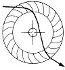
Its distinctive feature lies in the fact that water passes through the wheel twice. The peripheral blades are driven by a successively centripetal radial flow and centrifugal radial flow.
Its rotor is totally insensitive to leaves, twigs, algae, plastic bags, etc. They are ejected after half a turn by the combined effect of the water flow and centrifugal force.